|
Software systems and computational methods
Reference:
Filippova, K.A., Ayusheev, T.V., Damdinova, T.T., Tsidipov, T.T. (2024). Investigation of the stress–strain state of a composite blade in ANSYS WorkBench. Software systems and computational methods, 2, 41–52. https://doi.org/10.7256/2454-0714.2024.2.70712
Investigation of the stress–strain state of a composite blade in ANSYS WorkBench
Filippova Kseniya Anatol'evna
Senior Lecturer; Department of Aircraft and Helicopter Engineering; East Siberian State University of Technology and Management
670013, Russia, Republic of Buryatia, Ulan-Ude, Klyuchevskaya str., 40 V

|
ipq84@mail.ru
|
|
 |
Ayusheev Tumen Vladimirovich
Doctor of Technical Science
Associate Professor; Department of Engineering and Computer Graphics; East Siberian State University of Technology and Management
670013, Russia, Buryatia region, Ulan-Ude, Klyuchevskaya str., 40 V
|
|
atv62@bk.ru
|
|
|
Damdinova Tatiana Tsybikovna
ORCID: 0000-0002-3597-3262
PhD in Technical Science
Associate Professor, East-Siberian State University of Technology and Management
670000, Russia, Republic of Buryatia, Ulan-Ude, Klyuchevskaya str., 40 V
|
|
dtatyanac@mail.ru
|
|
|
Other publications by this author
|
|
|
Tsidipov Tsybik Tsirendorzhievich
PhD in Technical Science
Associate Professor; Department of Aircraft and Helicopter Engineering; East Siberian State University of Technology and Management
670013, Russia, Buryatia region, Ulan-Ude, Klyuchevskaya str., 40 V
|
|
sssibik@mail.ru
|
|
|
|
DOI: 10.7256/2454-0714.2024.2.70712
EDN:
XDTLCG
Received:
05/12/2024
Published:
05/25/2024
Abstract: In this paper, the static strength of a UAV blade made of composite material was calculated. Composite materials have an advantage over traditional materials (metals and alloys) in the field of aviation – gain in weight, low sensitivity to damage, high rigidity, high mechanical characteristics. At the same time, the identification of vulnerabilities in a layered structure is a difficult task and in practice is solved with the help of destructive control. Composite materials available in the ANSYS materials library were used in the modeling: Epoxy Carbon Woven (230 Gpa) Prepreg woven carbon fiber in the form of a semi–finished prepreg impregnated with epoxy resin carbon fiber with Young's modulus E=230 GPa and Epoxy Carbon (230 Gpa) Prepreg is a unidirectional carbon fiber prepreg impregnated with epoxy resin with a Young's modulus E=230 GPa. Modern software products, such as ANSYS WorkBench, allow comprehensive investigation of the layered structure. Several variants of blade designs with different fillers as the median material were investigated. The forward and reverse destruction criteria based on the Tsai-Hill theory were used. The influence of gravity was not taken into account. It is shown that the developed blade design meets the requirements. Balsa wood, pine, aspen and polyurethane foam were chosen as the middle material of the blade. Pine and aspen wood were selected according to the criteria of their availability and having the lowest density. The materials library of the ANSYS WorkBench software package used does not have characteristics for all of them, so the characteristics of the selected materials (pines and aspens) were added manually. For modeling and calculations in the ANSYS WorkBench program, such characteristics as density, axial elastic modulus, Poisson's coefficients, shear modulus and tensile and compressive strength limits are required.
Keywords:
composite material, blade, static strength, ANSYS WorkBench, stress, failure criterion, Tsai-Hill theory, carbon fabrics, fiberglass, middle fillers
This article is automatically translated.
You can find original text of the article here.
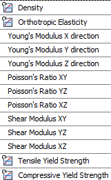
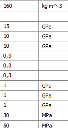
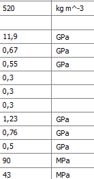
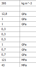
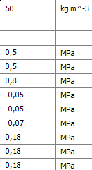
Introduction Composite materials have an advantage over traditional materials (metals and alloys) in the field of aviation - gain in weight, low sensitivity to damage, high rigidity, high mechanical characteristics. At the same time, the identification of vulnerabilities in a layered structure is a difficult task and in practice is solved with the help of destructive control. Modern software products, such as ANSYS WorkBench, allow comprehensive investigation of the layered structure. The topic of this work is relevant, the computing power of modern computers makes it possible to conduct research on increasingly complex parts and systems, analyze and select the composition of composite materials and structures of the propeller blade. In the study [1], a helicopter blade is considered, which has a different blade design from the one under consideration, in the work [2], a blade design containing a spar in the form of a multilayer fiberglass pipe and a honeycomb filler is considered. In the study [3], bench tests were carried out to determine the destructive load, the peculiarities of the nature of the destruction of the butt part were revealed, which is confirmed by the results of numerical research in this paper, given in the conclusions. Research objectives 1. To assess the stress-strain state (VAT) of a composite blade with a classical assembly: the middle material is balsa, layers of unidirectional carbon fiber prepreg are laid on top at an angle of 0 0, carbon fiber at an angle of -45 0, carbon fiber at an angle of 45 0. 2. Consider and calculate the VAT of blades with other types of median material: pine, aspen, and polyurethane foam. 3. Consider and calculate the VAT of a blade with a hybrid composite material: unidirectional fiberglass prepreg at an angle of 0 0, carbon fiber at an angle of -45 0, carbon fiber at an angle of 45 0. 4. To assess the safety margin according to the Tsai–Hill destruction criterion. Materials and methods The UAV blade under study is a sandwich structure, inside of which there is a middle material - balsa, layers are laid from bottom to top on the upper part of the balsa: a layer of unidirectional carbon fiber at an angle of 0 0 and two layers of woven carbon fiber at angles of -45 0, 45 0. On the lower surface of the balsa, the laying is performed similarly. The thickness of the composite woven layer is 0.16 mm, the thickness of the composite unidirectional layer is 0.08. The maximum length of the sample is 304.81 mm, the width of the sample varies from 15.26 mm to 52 mm. The mounting of the blade is cantilever. The centrifugal force of the Fsb and the lifting force of the Fpod act on the test sample. The load calculation was carried out as follows: Fcb=ml*?2*R, Fpod=mvzl*k, where the blade mass is ml = 0.06 kg, the angular velocity of the blade ? = 6000 rpm, the radius of rotation of the screw R = 300 mm, take-off weight of the UAV mvzl = 25 kg, The stock ratio is k = 1.5. Based on the results of the calculation, the following data were obtained: Fcb = 3553.058 N; Fpod = 367.5 5 N. Composite materials available in the ANSYS materials library were used for modeling: Epoxy Carbon Woven (230 Gpa) Prepreg woven carbon fiber in the form of a semi–finished prepreg impregnated with epoxy resin carbon fiber with Young's modulus E=230 GPa and Epoxy Carbon (230 Gpa) Prepreg is a unidirectional carbon fiber prepreg impregnated with epoxy resin with a Young's modulus E=230 GPa. The characteristics of balsa, pine, aspen and polyurethane foam are not available in the library of materials, so the characteristics [4] were added manually, such as density, axial elastic modulus, Poisson coefficients, shear modulus and tensile and compressive strength limits (Tables 1, 2) Table 1 – Characteristics of wood materials | Characteristics of the middle material | Balsa | Pine tree | Aspen |
| 
| 
| 
| 
| Table 2 – Characteristics of polyurethane foam | Characteristics of the middle material | Polyurethane foam | | 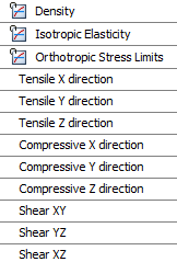
| 
| A model consisting of a blade and a balsa in the Parasolid format, built in the NX software package, is imported into ANSYS Workbench. The imported model is shown in Figure 1. 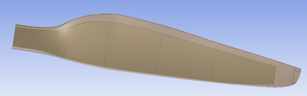
Figure 1 – Imported blade and balsa model The model is divided by a grid generator into a grid of finite elements, the element size of 1 mm is selected as a parameter. The laying of the composite material is set from top to bottom (Top - Down), the layers are modeled according to the following orientations at the corners of the laying: 45 0, -45 0, 0 0( fig. 2). 
Figure 2 – Layout of the composite blade Boundary conditions are set for the butt part (due to symmetry, we study only half of the blade) - cantilever sealing (prohibition of movement along all axes). The centrifugal force Ftb is applied to the center of mass. The lifting force F is uniformly set along the lower surface of the blade along the line of the ? chord of the blade. By analogy, blade variants with other median materials are modeled and studied: pine, aspen, polyurethane foam, and a blade variant with a unidirectional fiberglass prepreg instead of a unidirectional carbon fiber prepreg oriented at an angle of 0 0 is considered. Results The obtained results of the study of VAT of carbon fiber blades are presented in Table 3, VAT of glass-carbon fiber blades in Table 4, visualization of the study of VAT of the blade is shown in Figure 3. The maximum deformations of the blade are shown as a histogram for comparative analysis (Fig. 4).
Table 3 - Calculation of the VAT of a carbon fiber blade: total deformation, deformations along the X, Y, Z axes | The middle material | Maximum deformation, mm | Deformation along the X-axis,mm | Y-axis deformation, mm | Deformation along the Z axis, mm | | Balsa | 0,72409 | 0,18478 | 0,008113 | 0,087863 | | Pine tree | 0,83737 | 0,20401 | 0,0090682 | 0,096759 | | Aspen | 0,82147 | 0,19924 | 0,0088863 |
0,094065 | | Polyurethane foam | 1,7645 | 0,39324 | 0,021362 | 0,33716 | Table 4 - Calculation of VAT of a glass-carbon fiber blade: complete deformation, deformations along the X, Y, Z axes | The middle material | Maximum deformation, mm | Deformation along the X-axis,mm | Y-axis deformation, mm | Deformation along the Z axis, mm | | Balsa | 0,81438 | 0,2139 | 0,010093 | 0,077528 | | Pine tree | 0,94891 | 0,23745 |
0,01126 | 0,082537 | | Aspen | 0,93103 | 0,23106 | 0,010965 | 0,080557 | | Polyurethane foam | 1,9255 | 0,47155 | 0,02847 | 0,32144 | 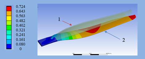
Figure 3 - Deformation (mm) of the carbon fiber blade (middle body – balsa). 1 - Initial position of the blade, 2 - Deformed blade An essential feature of the assessment of the bearing capacity of composite structures is the layered VAT analysis of the composite structure, which consists in analyzing the VAT of each layer. In this work, the analysis was performed in layers: the maximum and minimum stresses were determined, and a mapping of vulnerabilities in each layer was obtained. 
Figure 4 - Maximum blade deformations The results of the layered study for the carbon fiber blade are presented in Table 5 and Figures 5-7, for the glass-carbon fiber blade in Table 6. For convenience, the layer encoding was used: layer 1 – layer oriented at an angle of 45 0, layer 2 – layer oriented at an angle of -45 0, layer 3 – layer oriented at the angle is 0 0. Table 5 – Maximum and minimum stresses in layers for a carbon fiber blade |
| Blade VAT, ? max /? min (Mpa) | | The middle material | Layer 1 (Carbon Fiber) | Layer 2 (Ugletkan) | Layer 3 (Single-pressure carbon fiber.) | | Balsa | 68,88 / -24,365 | 67,072 / -61,839 | 266,39 / -28,567 | | Pine tree | 71,086 / -26,369 | 73,13 / -69,699 | 290,04 / -31,634 | | Aspen | 70,08 / -26,189 | 71,786 / -66,848 | 282,16 / -31,896 |
| Polyurethane foam | 123,79 / -43,03 | 123,85 / -142,67 | 526,16 / -78,56 | Table 6 – Maximum and minimum stresses in layers for a glass-carbon fiber blade | | Blade VAT, ? max /? min (Mpa) | | The middle material | Layer 1 (Ugletkan) | Layer 2 (Ugletkan) | Layer 0 (Single-pressure fiberglass) | | Balsa | 81,52 / -25,988 | 61,191 / -49,038 | 71,009 / -9,9571 | | Pine tree | 85,61 / -28,371 |
62,207/ -54,558 | 76,645 / -11,09 | | Aspen | 84,009 / -28,149 | 65,716 / -53,126 | 74,83 / -11,111 | | Polyurethane foam | 145,28 / -45,175 | 125,4 / -133,25 | 139,31 / -22,375 | 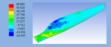
Figure 5 – Stress pattern (MPa) in layer 1 (at an angle of 45 0) of a carbon fiber blade (middle body – balsa) 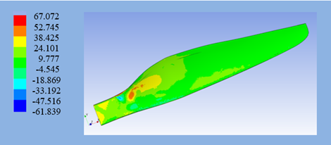
Figure 6 – Stress pattern (MPa) in layer 2 (at an angle of -45 0) of a carbon fiber blade (middle body – balsa) 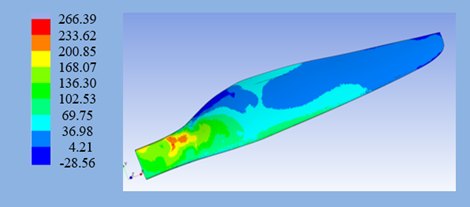
Figure 7 – Stress pattern (MPa) in layer 3 (at an angle of 0 0) of a carbon fiber blade (middle body – balsa) To assess the strength, the inverse safety factor was used, which shows how many times the acting stresses are less than the permissible ones [5]. Destruction occurs when IRF>1.  , ,
where RF is the safety factor, it is defined as the ratio of the destructive load to the applied load. Quite a lot of strength criteria have been developed for composites [6,7] and each of them reflects certain features of destruction. The above safety factor is based on the Tsai-Hill criterion, which is an analytical approximation of the test results of a unidirectional layer under various types of loading. This criterion has the following form: 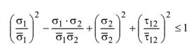
where ?1, ?2, ?12 are normal and tangential stresses, ?1, ?2, ?12 are their limit values.
Table 7 shows the inverse safety factors for a carbon fiber blade with different variants of the median material, Table 8 shows the inverse safety factors for a glass-carbon fiber blade with different variants of the median material (the value of the coefficient exceeding the permissible stresses is highlighted in italics, visualization of this value is shown in Figure 8). Table 7 – IRF Summary table for carbon fiber blade layers with different variations of median materials | Carbon fiber blade, the middle material | The number of the most stressed layer | Maximum IRF coefficient | | Balsa | 3 | 0,58 | | Pine tree | 3 | 0,65 | | Aspen | 3 | 0,63 | | Polyurethane foam | 3 | 1,38 | Table 8 – IRF summary table for layers of glass-carbon fiber blades with different variations of the middle materials
| Glass is a carbon fiber blade, the middle material | The number of the most stressed layer | Maximum IRF coefficient | | Balsa | 1 | 0,13 | | Pine tree | 1 | 0,14 | | Aspen | 1 | 0,15 |
| Polyurethane foam | 1 | 0,38 | 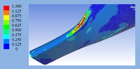
Figure 8 – Carbon fiber blade (the middle body is polyurethane foam). IRF in the most stressed layer of carbon fiber (layer 3) Conclusions 1. The VAT assessment of a composite blade with a classic assembly was carried out: the middle material is balsa, layers of unidirectional carbon fiber prepreg are laid on top at an angle of 0 0, carbon fiber at an angle of -45 0, carbon fiber at an angle of 45 0. The middle material, balsa, is the best option in terms of maximum deformations, deformations along the x, y, z axes. 2. Calculated the VAT of the blade with other types of median material: pine, aspen, polyurethane foam. Among the considered medium materials, polyurethane foam is the worst option. The indicators for the maximum deformation of the polyurethane foam blade exceed the same indicator of the balsa blade by 2.4 times. The difference in deformations between a blade with balsa and a blade with aspen or pine as the median material is no more than 15%, which is a satisfactory result, given the cost and inaccessibility of balsa material, unlike common pine and aspen. 3. Calculated the VAT of the blade with a hybrid composite material: unidirectional fiberglass prepreg at an angle of 0 0, carbon fiber at an angle of -45 0, carbon fiber at an angle of 45 0. The composite material works in layers and stretches. and for compression. The best option for the middle material is balsa, however, the deterioration of mechanical characteristics (tensile stress, compression) in layers for pine and aspen materials does not exceed 20%, which is a satisfactory result, given the cost and inaccessibility of balsa material, unlike common pine and aspen. 4. The safety margin of all blade variants has been evaluated. The analysis of the most stressed sections in layers revealed that the strength of the blade is not provided with the option: carbon fiber blade, the middle material is polyurethane foam. A section with an IRF = 1.38 coefficient appears in the layer at an angle of 00, which exceeds the permissible voltage by 38%. The load that caused the destruction of fibers in any layer of the composite structure is considered to be the limit for the entire structure. This makes it possible to determine the maximum possible bearing capacity of the composite structure under study. Thus, the VAT assessment of a layered KM structure is based on the VAT assessment of a unidirectional layer. It should be taken into account that the obtained simulation results need experimental verification. The study was supported by a grant from the Ministry of Education and Science of the Republic of Buryatia (Agreement No. 413 dated 12/21/2023).
The article is published in the version approved by the reviewers (after receiving a positive review recommending the manuscript for publication), with corrections made by the author (submitted after receiving editorial comments, if any).
The review is published in open access directly after the text of the article itself. All versions of the author's corrections are stored in the publisher's repository and may be available upon request by authorized organizations.
Read the review for this article
References
1. Feng, G., Dumansky, A.M. & Ruslantsev, A.N. (2016). Study of the static strength of a composite helicopter blade. Proceedings of the Second International Conference. Deformation and Fracture of Composite Materials and Structures, 196-198.
2. Sidorov, I.N., Gorelov, A.V. & Nikolaev, E.I. (2015). Calculation of stress-strain and limit states of a composite helicopter rotor blade under various flight modes, taking into account damage in the butt section. XI All-Russian Congress on Fundamental Problems of Theoretical and Applied Mechanics, 3453-3457.
3. Burtsev, B.N. & Tyutyunnikov, N.P. (2012). Features of the stress-strain state of the butt part of the main rotor blade. Mechanics of composite materials and structures, 18(4), 552-561.
4. Glebov, I.T. (2018). Physics of wood. Ekaterinburg: UGLTU.
5. Pervushin, Yu. S., & Zhernakov, V. S. (2008). Fundamentals of mechanics, design and technology for manufacturing products from layered composite materials. Ufa: Ufimsk. state aviation tech. univ.
6. Hill, R. (1966). Theory of mechanical properties of fibrous composite materials. Mechanics, 2, 131-149.
7. Vasiliev, V. V. (1988). Mechanics of structures made of composite materials. Moscow: Mechanical Engineering.
Peer Review
Peer reviewers' evaluations remain confidential and are not disclosed to the public. Only external reviews, authorized for publication by the article's author(s), are made public. Typically, these final reviews are conducted after the manuscript's revision. Adhering to our double-blind review policy, the reviewer's identity is kept confidential.
The list of publisher reviewers can be found here.
The article is devoted to the study of the stress-strain state (VAT) of a composite blade with various median materials, such as balsa, pine, aspen and polyurethane foam, using the ANSYS WorkBench software product. This is an important and relevant topic in the field of materials science and aeronautical engineering, as composite materials are becoming more and more in demand due to their advantages over traditional materials. The authors performed numerical modeling of the VAT of a blade with different types of median materials using finite element methods in ANSYS WorkBench. The paper describes in detail the modeling process, including geometric parameters, materials and loading conditions. This allows you to reproduce the study and verify its results in practice. The relevance of the work is due to the increasing use of composite materials in the aviation industry. Composites provide a significant reduction in the weight of structures while maintaining or improving their mechanical characteristics. In this context, the study of the VAT of a composite blade is of great importance for the development and optimization of aviation components. The scientific novelty of the article lies in an integrated approach to the study of the VAT of a composite blade with different types of median materials and hybrid composites. For the first time, the authors conduct a detailed analysis of the effect of various median materials on the VAT of the blade, which allows us to determine the optimal combinations to achieve the best strength and stiffness characteristics. The article is written in a scientific style, logically structured and consistently presents the material. The introduction clearly defines the goals and objectives of the study. The main part contains a detailed description of the methodology and results, supported by illustrations and tables, which facilitates the perception and analysis of data. The conclusions are substantiated and confirmed by the results of numerical modeling. The study showed that the most optimal median material for a composite blade is balsa, which provides the best VAT rates. Polyurethane foam blades have shown worse results, which makes this material less preferable. The analysis of hybrid composites also revealed significant advantages of using balsa compared to pine and aspen. The article is of interest to scientists and engineers working in the field of materials science, aviation and engineering industries. The study contains valuable data and techniques that can be used for further research and practical application in the development and optimization of composite structures. The article is an important contribution to the field of composite materials research and their application in aviation. It contains significant theoretical and practical results that can be useful for the scientific community and industry. For the further development of this work, several directions can be proposed. First of all, laboratory tests of the studied composite blades should be carried out to confirm the numerical data. The experimental results will allow us to verify the adequacy of the model used and clarify its parameters. In addition, it is important to consider the possibility of using other types of composite materials, such as carbon-Kevlar and carbon-basalt composites. Comparing their characteristics with the materials already studied can reveal additional advantages. The analysis of the dynamic behavior of composite blades under the influence of various loads, including vibration and shock loads, is also an important area. This will help determine the durability and reliability of the blades in real operating conditions. Optimization techniques should be applied to improve the blade design, which may include changing the shape, size, and location of the composite layers to achieve the best strength and stiffness with minimal weight. Equally important is the study of the behavior of composite blades under various operating conditions, such as extreme temperatures, humidity and exposure to aggressive media. This will help to assess the durability and stability of materials in various climatic conditions. It is also important to simulate the propagation of cracks and damage in composite blades. This will allow us to develop methods for early detection and prevention of damage, which will increase the reliability and safety of operation. An economic analysis of the application of various composite materials, taking into account the cost of materials, production technology and operating costs, is also necessary. This will help you choose the best solution in terms of cost and efficiency. Based on the obtained data and analysis, recommendations for the production of composite blades should be developed, including the choice of materials, laying methods and technological parameters. This will help to improve the quality and reduce the cost of production.
|

 Eng
Eng


